Circuit Wizard - brings electronics into STEM
Electronics is a focus subject that links together the science and mathematics strands as well as Design and Technologies and Digital Technologies.
Easy to see this connectivity
Science - temperature, power, current, voltage, potential difference, semiconductors, band gap of leds, junctions, fuse, heating of materials. Logic gates, combinations, interfacing, capacitors, basic components
Mathematics - data with op amps, graphing, errors, calculations with Ohms law, parallel and serial circuits’
Coding ; flowchart and planning, inputs, outputs, decision making, logic operation, subroutines, processes, mathematical operations, floating point, integer, digital representation.
Design and Technologies/Digital: making the systems, packaging, looking at design of a total system, supercapacitor energy storage.
Sustainability - make a gardening control system, weather station greenhouse controller, solar panel heat collection and storage to save power etc.
Circuit Wizard uses an impressive range of working environments to convert many abstract concepts to reality.
Mechanical systems can also be studied.


This is an ideal starting point for young students starting out in electronics.
Select the components from the parts tray and join with wires. The operation of the circuit is simulated.
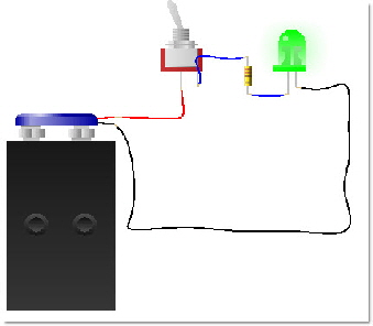
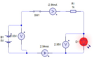
This circuit is a basic led light. The battery connects to a switch and a current limiting resistor.
 The advantage of simulation: Connect the led backwards and see if it works. Hard to do in real life. Change the value of the resistor and see if the brightness of the led deoends on the resistor value. Make a link to the concept of current.
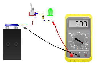
You can add real world meters to measure current, voltage etc.
This mode of operation is ideal for young students and can serve as a good path through the components so they can be visualised prior to using breadboards or circuit boards.
- Elementary circuit - real world objects linked together
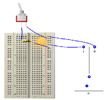
- Breadboard to reflect a real component placement
- Schematic entry with symbols for components
- PCB - printed circuit board with testing of operation
Breadboard operation
Breadboards with the array of holes are a common object in electronics or science laboratories.
Components are pushed into the holes and wires are used to link to components on the board or to external devices such as switches and motors.
This environment is an excellent progression from the elementary circuit and shows the way ahead to printed circuit boards.
Breadboards are useful for rapid prototyping and development.
Circuit Wizard supports a large number of devices including meters and oscilloscopes.
Schematic Entry
Placing images that represent the electronic components and then linking them defines a virtual circuit. It is like a plan for the system and this schematic entry is the most common way of designing a a circuit in most of the design packages.
CircuitWizard goes one step further with the option of simulating the operation of the circuit and placing a large number of measuring tooks in the circuit.
For example, a common point of confusion is the current and voltage in a circuit. It is easy to place these symbols into the circuit and observe the values when the circuit is operational.
CircuitWizard also allows the placing of a graphical screen that shows a graph of the measured variable in a time plot. Ideal link to science and mathematics activities.
Once the circuit is operating in the correct manner it is easy to transfer into the PCB Design section and place components and tracks to make a real product.
PCB Entry
A printed circuit board is the most common foundation for electronics systems. Components are placed on the board and the interconnecting tracks are part of the copper layer. These have been defined by a number of processes - mostly chemical etching of the tracks with a soecial mask that leaves the tracks intact but removes the adjoining copper. We do a similar process by engraving.
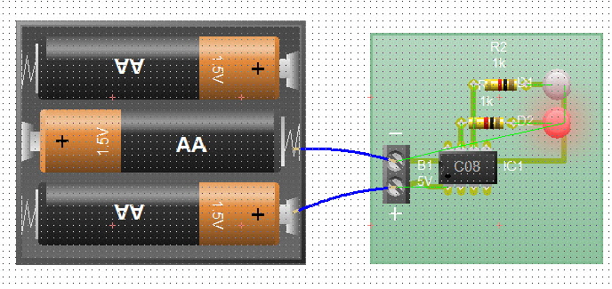
This figure shows the simple LED circuit placed on the green area. Tracks can be seen and the switch and battery are external components connected by wires.
Again, the design and simulation process is transferred and now the operation of the final PCB can be verified.
All these steps make it easy to teach electronics in a consistent manner.
Electronics is a very exciting subject and has progressed through a number of stages in technology. Initailly mist circuits had a number of integrated circuits that could be set up in special ways to operate a system. These circuits came from transistors and other devices.
However, as more and more features are needed in systems we have seen the growth of embedded microcontrollers that can be programmed with a set of instructions to operate some device. Most machines and systems have one or several devices.
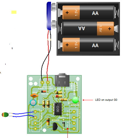
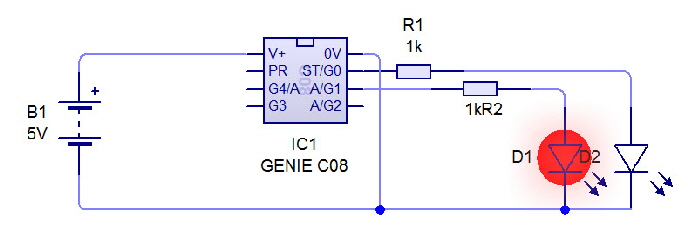
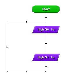
Circuit Wizard introduces the micro via the innovative Genie programming vision. The device is used to define a circuit in the schematic editor and then programmed with simple flow chart structure.
The final pcb can also be simulated with the flow chart program. Students can also directly define the program with the BASIC programming language.
Intellecta TECHNOLOGIES
Intellecta TECHNOLOGIES